


TOP 9 sensors on the ship for monitoring its performance
9 different sensors that can be found in one form or another on each vessel, and information from which is used not only by the captains of the vessel to make decisions on maneuvering but also by the shipping company to monitor vessel performance.
Sensors are a type of equipment that can usually be seen on any cargo ship, and therefore the quality of the data obtained from them is always complete and accurate. In this article, we will consider 9 different sensors that can be found in one form or another on each vessel, and information from which is used not only by the captains of the vessel to make decisions on maneuvering, but also by the shipping company to monitor vessel performance.
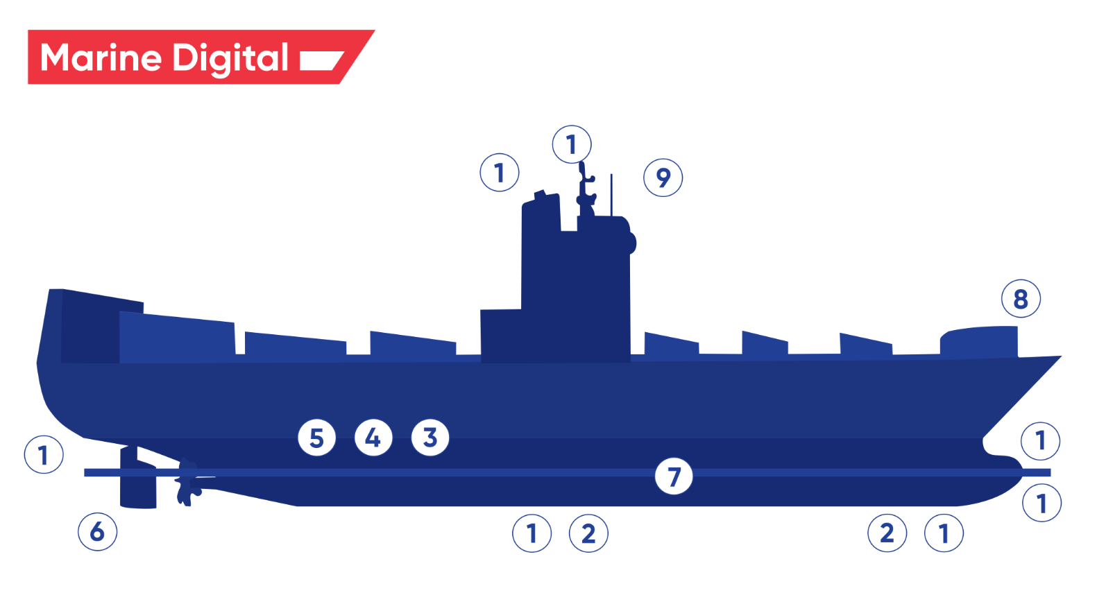
This figure shows a drawing of the ship with positions of data logging sensors as on the following list:
1. Speed log
2. Echo sounder
3. RPM and torque meter
4. Shaft motor
5. Thrust meter
6. Rudder indicator
7. Stabilizer fins
8. Wind anemometer
9. GPS
1. Speed log
2. Echo sounder
3. RPM and torque meter
4. Shaft motor
5. Thrust meter
6. Rudder indicator
7. Stabilizer fins
8. Wind anemometer
9. GPS
1. Speed log
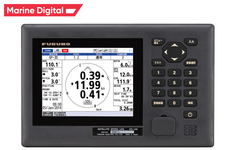
The speed log is an important source of data when calculating performance. Sensor accuracy depends on calibration and manufacturer. An offset between the speed log reading and the actual speed indicates a need for calibration. In terms of accuracy, different manufacturers of speed logs provide different information.
There are several environmental factors that affect speed log measurements:
There are several environmental factors that affect speed log measurements:
- Water clarity - Velocity measurement in water depends on acoustic reflection from solid particles in the water, such as microorganisms or suspended dirt. In very clean water, the number of diffusers may not be sufficient for adequate signal return.
- Aeration - Aerated water below the transducer can reflect sound energy that could be misinterpreted as the return of the seabed. Sailing in bad weather or non-laminar flow around the sensor can be a source of this effect.
- State of the Sea - Following the sea results in a variable change in the speed of the vessel. This causes fluctuations in the measured speed.
2. Echo sounder
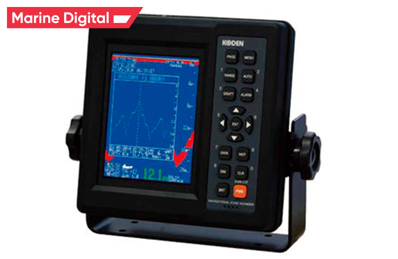
The ship has two sensors - one in the bow and one at approx. accomodationt. The frequency ranges for the transducer are in the range of 28 to 210 kHz, and the measurement accuracy is about 2.5% of the measured depth.
Environmental factors that can affect measurements:
Environmental factors that can affect measurements:
- The state of the sea. Strong rolling in bad weather.
- Sea water temperature Increase in water temperature in several sea areas. Hot water discharges from power plants.
- Noise from bow thrusters, vibration of the main engine and reverse rotation of the propeller.
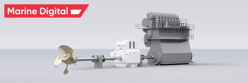
3. RPM and torque meter
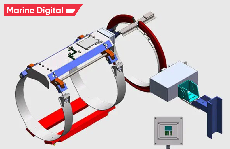
Propeller torque is usually measured using strain gauges. Load cells are mounted on a propeller shaft and measure the elongation of the shaft under the action of forces and moments. Deformations transform into stresses that determine the deformation of the shaft. Typical propeller shaft torque measurements are in the order of 330 microstrains, and strain gauges are capable of detecting changes in the order of 1.5 microstrains.
The torque meter measures torque with strings (strain gauges) and speed with a laser. Shaft rings are installed and placed as close to the main engine as possible. The measurement accuracy is about 0.5%, and the update period for measurement results can be varied. The speed / torque meter is calibrated on installation and, depending on the manufacturer and type, different calibration intervals and methods are offered. The torque meter and speed measurements are used to determine the shaft power.
The torque meter measures torque with strings (strain gauges) and speed with a laser. Shaft rings are installed and placed as close to the main engine as possible. The measurement accuracy is about 0.5%, and the update period for measurement results can be varied. The speed / torque meter is calibrated on installation and, depending on the manufacturer and type, different calibration intervals and methods are offered. The torque meter and speed measurements are used to determine the shaft power.
4. Shaft motor
A gross motor is an electric motor that transfers power to a shaft. The specific motor is in the 6 MW power range and the shaft power is transmitted in the following speed range:
- 34 - 85 rpm with linear power of 2.3 MW up to 6 MW with constant torque
- 85 - 99 rpm at a constant power of 6 MW
5. Thrust meter
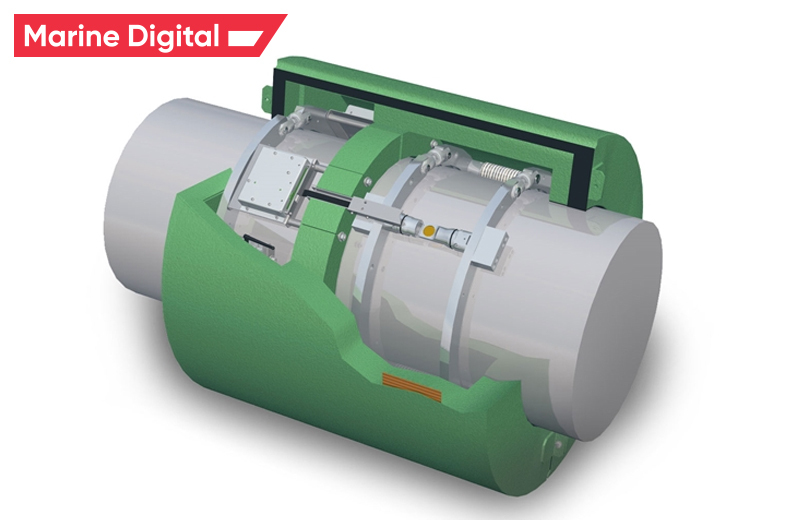
If thrust were measured with strain gauges, the thrust measurements would be in the order of 35 microstrains, which would lead to too much inaccuracy, and therefore alternative methods should be used. Therefore, high definition sensors are designed and used in the thrust meter.
The thrust meter measures RPM, torque and shaft force. The measurement accuracy is in the range of 0.1%, and the update period of the measurement results can be varied.
The thrust meter measures RPM, torque and shaft force. The measurement accuracy is in the range of 0.1%, and the update period of the measurement results can be varied.
6. Rudder indicator
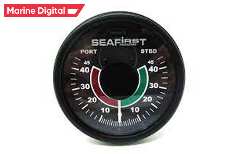
The rudder indicator continuously measures the rudder angle, and the measurement accuracy is +/- 0.5 ° at angles near the midship and +/- 1.5 ° above the rudder.
The rudder direction may constantly shift during service. The reasons for this can be various:
The rudder direction may constantly shift during service. The reasons for this can be various:
- Index error in the rudder angle measuring device.
- Constant rudder angle to counteract right-hand propeller rotation.
- A permanent yaw effect caused by the ship's hull or wind action on the superstructure and container cargo while sailing.
7. Stabilizer fins
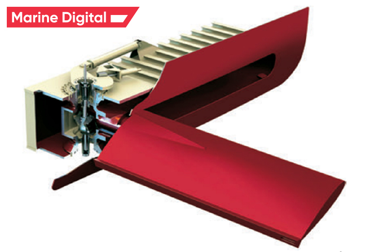
The stabilizer ribs counteract the roll of the boat while sailing. They are installed on both sides of the vessel with a hold turn of approx. 3.5 m above the keel and in the aft part of the hold. They are installed at an angle of 25 ° to the horizontal and, when not in use, retracted into the ship's hull. With use, the angle of attack of the fins changes and this change is continuously measured.
Ribbed stabilizers are rarely used.
Ribbed stabilizers are rarely used.
8. Wind anemometer
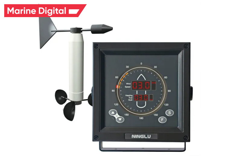
The wind anemometer is a helical type with a blade to measure the direction. It is installed in the bow of the mast, which is in accordance with the general rule that anemometers should be placed as high and further on the ship as possible so that there is no distortion of the air flow entering the anemometer.
The measurement accuracy is about +/- 0.3 m / s or 1% of the wind speed and +/- 3 ° wind direction. The accuracy is determined by the calibration range of the anemometer.
The relative wind speeds are shown in Figure 49 with a predominant distribution in the range of 8 to 16 m / s.
The anemometer measures the relative wind speed and direction. This is converted into true wind speed and direction in the onboard recording system.
9. GPS
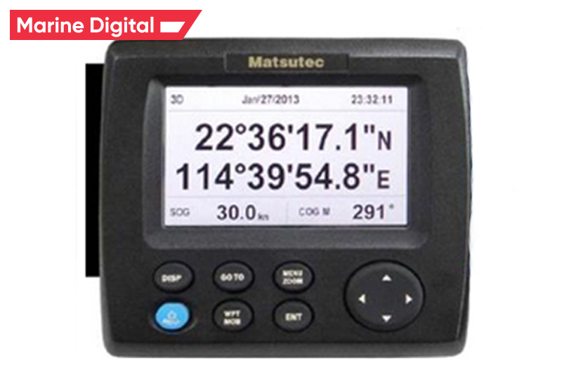
GPS unit on board is a part of GNSS (Global Navigational Satellite System) which provides users with positioning, navigation, and timing services.
The most common GNSS in the world are GPS (USA), GALILEO (EU), and GLONASS (RU) using geostationary satellites to provide position accuracy up to 3m and more.
It is recommended to operate GPS units onboard on different systems due to new cyber security threats jamming and spoofing which can cause:
The most common GNSS in the world are GPS (USA), GALILEO (EU), and GLONASS (RU) using geostationary satellites to provide position accuracy up to 3m and more.
It is recommended to operate GPS units onboard on different systems due to new cyber security threats jamming and spoofing which can cause:
- Signal offset in position and heading
- Lost the signal
Vessel performance monitoring & Fuel optimization system
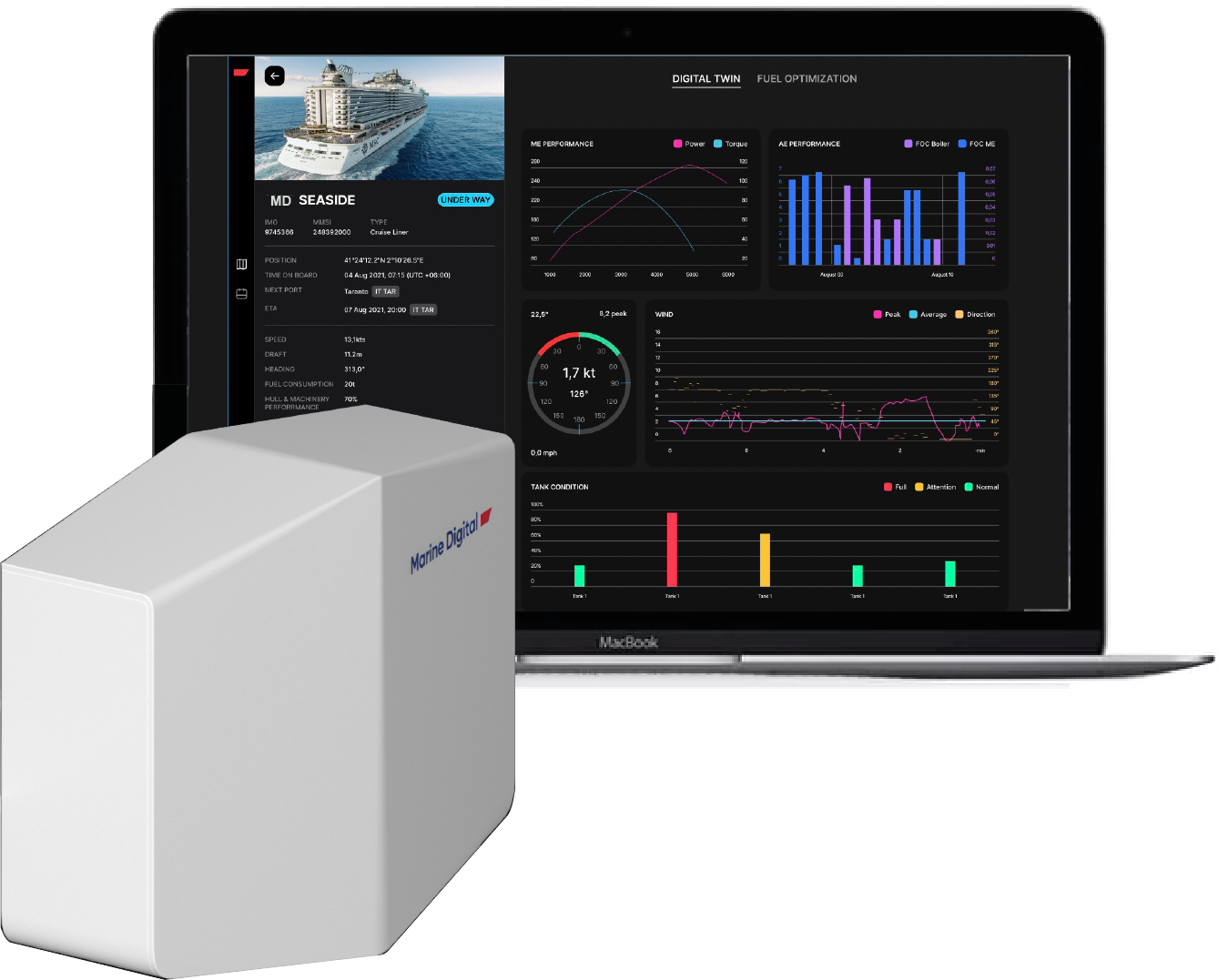
In Marine Digital we are solving every problem that may occur during vessel performance monitoring. This includes not only data gathering from different vessels, but also processing and interpretation of the received data, creation of convenient reports, delivery of charts to the vessel's navigation system (ECDIS), as well as recommendations for the best route according to weather, fuel consumption and other data from the ship.
Using machine learning to build the optimal route and speed of the vessel based on the analysing of data from the vessel, weather conditions and currents allows us to reduce the fuel consumption due the route. Vessel burns up to 30 tons per day and depends on many factors, such as the weather, currents and also navigation.
In Marine Digital we during the development process have formed 4 solutions that are suitable for charters, shipowners and fleet managers of different types of vessels for:
Read also 21 Types of Navigation Equipment onboard Ships

TOP 5 factors contributing to lower fuel costs for Shipping companies
Get a presentation with a full description of the features and free pilot project with trial of Marine Digital FOS for 2 months
"Clicking the button, you consent to the processing of personal data and agree to the privacy policy"

Get an overview "The Pathway to Zero Carbon Shipping:
IMO Compliance and CII Optimization through SEEMP" on email and download it for FREE! Leave your email now!
"Clicking the button, you consent to the processing of personal data and agree to the privacy policy, as well as consent to subscribe to the newsletter. "
Аdvantage of Fuel Optimization System from Marine Digital:

Marine Digital FOS can be integrated with other system and third-party's solutions through the API. To implement vessel performance monitoring for any vessel, we are using mathematical algorithms, machine learning and the same equipment as in FOS. The more data we collect from vessels, the more precise reports and recommendations our system will perform according to your individual requirements in fleet management.
If you have any questions about the solutions and the Marine Digital System platform, write to us, we will be happy to answer
If you have any questions about the solutions and the Marine Digital System platform, write to us, we will be happy to answer

Increased business process speed

Reducing to zero the number of errors

Best offer to the clients

Reduction in operating expenses
Have a questions?

